
A single GPU rack already draws more than 2,000 amps
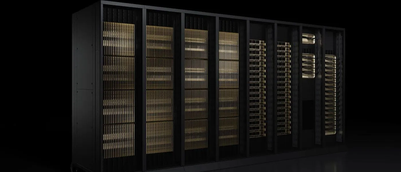
Take an NVIDIA GB200 NVL72 rack, deployed by many cloud providers since 2025. Its 72 GPUs draw about 120 kW. To feed them, NVIDIA puts eight 33 kW power shelves in the same cabinet, doubled so that a failure does not stop the job. They convert the building’s AC power into 50 to 51 V DC, distributed along the rack by a copper bar, the busbar A rigid conductor, usually copper, that distributes supply current along a rack. In current NVIDIA racks it carries about 50 V DC to each tray; its cross-section must grow with the current it carries. .
At 50 V, 120 kW means 2,400 amps. The next generation, GB300 NVL72, is rated at 135 kW and up to 155 kW at peak according to Lenovo, or roughly 3,100 A. NVIDIA is then preparing racks it describes as approaching a megawatt. At that point the problem changes: it is no longer about finding a bigger power supply, it is about moving the current at all.
That is the reason behind the 800 VDC architecture NVIDIA introduced on May 20, 2025, then detailed in two white papers. Google, Meta and Microsoft have been working on a ±400 V variant within the Open Compute Project (OCP), the organization where large operators publish their hardware specifications. In August 2026, NVIDIA, Google and Microsoft announced that they were coordinating this work.
This article explains why high-voltage DC is taking over, what it changes in the power chain, the problems it introduces and what actually exists in September 2026. It relies on vendor documents, public specifications and independent analyses. LeCompute did not measure any equipment: the calculations are reproducible and their assumptions are listed in “Sources and method”.
Six conversions between the grid and the GPU
Follow the electricity from the site entrance. The utility delivers medium voltage, for example 34.5 kV in the United States or 20 kV in France. A transformer steps it down to 400, 415 or 480 V three-phase AC. An uninterruptible power supply (UPS) then protects the servers against outages: in its double-conversion form, it rectifies the power to DC to charge its batteries, then inverts it back to AC.
Power reaches the racks through busways or cables. Inside the rack, the power shelves convert it to 50 or 54 V DC. On each compute tray, an intermediate bus converter steps that 54 V down to 12 V or 6 V. Finally, voltage regulators next to the GPU, the VRMs, deliver less than one volt at thousands of amps to the silicon.
Every conversion loses some energy as heat. To get an order of magnitude, you can multiply the best published efficiency of each stage. Table 1 does this for a fully loaded rack, assuming 1% losses in cables and busways.
| Stage | Efficiency used | Cumulative |
|---|---|---|
| Medium-voltage transformer | 99.5% | 99.5% |
| Double-conversion UPS | 97% | 96.5% |
| Cables, busways, panels (assumption) | 99% | 95.5% |
| Rack shelf, AC to 54 V | 97.5% | 93.2% |
| Bus converter, 54 V to 12 V | 98% | 91.3% |
| VRM, 12 V to GPU core | 89% | 81.3% |
Two things stand out. Losses concentrate in the UPS, the rack shelves and above all the last regulator, which alone costs about ten points. And that final stage stays the same with 800 V: whatever voltage runs through the building, something still has to get down to less than one volt next to the GPU. NVIDIA writes that the current chain’s end-to-end efficiency “can be less than 90%”, without saying whether that includes the final regulator.
Why 54 V is running out
Electrical power is voltage times current. To carry the same power at a lower voltage, you need more current. That current heats the conductors: resistive (Joule) losses equal the resistance times the square of the current. Double the current through the same copper and you quadruple the heat to remove.
Here is what that means for a 1 MW rack, the target NVIDIA and Google have set for the end of the decade.
At 54 V, a 1 MW rack draws about 18,500 amps. The same megawatt at 800 V needs only 1,250 A, fifteen times less. For the same copper cross-section, resistive losses fall by (800 / 54)², or about 220 times. Anyone who knows power transmission recognizes the principle: raise the voltage to move energy without turning it into heat. The difference here is that the “long distance” fits inside one room, and the binding constraint is space.
The number becomes concrete with copper. An air-cooled copper conductor carries on the order of 2 A per square millimeter to stay at a reasonable temperature. At 54 V, one megawatt then needs more than 9,000 mm² of cross-section per conductor, about 83 kg of copper per meter of bar. At 800 V, 625 mm² is enough, or 5.6 kg per meter. NVIDIA puts the busbar of a 1 MW rack at 54 V at “up to 200 kg”. Our calculation shows that figure is plausible for a two-meter bar sized somewhat more tightly; it would still dissipate about 4 kW at full load, versus about twenty watts for the same copper at 800 V.
Space matters as much as copper. A 33 kW power shelf takes one rack unit. A megawatt would need about thirty of them, about sixty with redundancy: NVIDIA indeed quotes “up to 64 U” of power shelves for a megawatt Kyber rack, more than an entire cabinet. Those units would sit in the most valuable part of the rack, where the copper NVLink NVIDIA's proprietary GPU-to-GPU interconnect. NVLink 5 (Blackwell) reaches 1.8 TB/s bidirectional per GPU; NVLink 6 (Rubin) doubles that to 3.6 TB/s. With NVSwitch, it accelerates GPU-to-GPU transfers and collectives; memory remains physically distributed, and remote access does not have the cost of local HBM. cables connect the GPUs. NVIDIA’s white paper puts it plainly: with short-reach copper links, maximum performance is tied to maximum power density.
Microsoft quantified the benefit of moving power out of the rack as early as October 2024: 15% to 35% more accelerators per rack, in the Mt Diablo project run with Meta. Google talks about using “the entire IT rack” for its processors. This is the first argument for 800 V, and the strongest one.
What the 800 V chain changes
NVIDIA proposes converting power once, upstream, then distributing 800 V DC all the way to the racks. Eventually, a medium-voltage rectifier or an SST Solid-State Transformer. It replaces the 50/60 Hz transformer with a power-electronics chain: rectifying the medium-voltage input, converting at high frequency through a small isolation transformer, then delivering direct current. turns grid power directly into 800 V DC. The solid-state transformer replaces the 50/60 Hz iron-core unit with power electronics that operate at high frequency, using a much smaller transformer.
The 800 V then runs through the room on two conductors plus a protective earth, instead of three phases, a neutral and a ground. Inside the rack, NVIDIA plans for Kyber a converter that goes straight from 800 V to 12 V with a fixed 64:1 ratio. It removes two intermediate stages. The October 2025 white paper credits it with 1% more efficiency and 26% less area than a multistage approach.
Semiconductor vendors showed their demonstrators in 2026. Infineon reports 98.2% peak and 97.1% full-load efficiency for a 6 kW, 800 V to 12 V board. Navitas reports 98.1% at full load for a 10 kW, 800 V to 50 V converter switching at 1 MHz. Texas Instruments proposes a two-stage path, 800 V to 6 V then to the core, with 97.6% peak efficiency for the first stage. These are vendor figures for reference designs.
The split between materials follows from the voltage each part must block. Silicon carbide (SiC) dominates wherever more than 1,000 V must be blocked: rectifiers, SSTs, protection. 650 V gallium nitride (GaN) goes into the high-frequency rack converters, with several transistors stacked in series because no mainstream GaN device holds 800 V alone with margin. These are the building blocks of 800 V electric vehicles and solar inverters, two industries that made them available in volume.
The efficiency gain depends on the baseline
In its May 2025 post, NVIDIA announced “up to 5%” better end-to-end efficiency, “up to 70%” lower maintenance costs and “up to 30%” lower total cost of ownership. None of the three figures comes with a calculation. The 18-page white paper published in October does not repeat them, and the 2026 white paper announces a future assessment of business value and reliability.
To see where a 5-point gain can come from, take Table 1 down to the 12 V output: about 91.3% with a double-conversion UPS. Replace the upstream part with a 99% rectifier, keep 0.5% distribution losses and use a 98% converter from 800 V to 12 V. The result is about 96.5%, or 5.2 points better. NVIDIA’s figure is consistent with that baseline.
Now change just one element of the AC chain: a UPS running in eco mode at 99% instead of 97%, as several vendors offer. The AC chain then reaches 93.2% at 12 V, and the 800 V advantage drops to 3.3 points. A large part of the gain comes from eliminating double conversion, which some operators have already done in AC, for example with battery backup units placed directly in the racks.
SemiAnalysis published on May 26, 2026 the only detailed model we found. Its AC baseline reaches 82.0% across seven stages. The first deployment, a power rack installed next to existing IT racks, only raises that to 83.7%. It takes native 800 V racks and then SSTs to reach 87.4%. These are model estimates, not measurements.
This debate has happened before. In 2008, Lawrence Berkeley National Laboratory demonstrated 380 V DC distribution and measured 5% to 7% savings against the best AC systems, and up to 28% against a modeled “typical” system. Neil Rasmussen, at APC and then Schneider Electric, replied that the gap with a well-designed AC system was about 1% at full load. Each side was right about its own baseline. 380 V DC never took hold in large Western data centers, for lack of servers, breakers and standards, while Tencent, Alibaba and Baidu have used 240 V DC for years.
Two things have changed since. Rasmussen assumed diverse loads and IT equipment that could not run on DC; a room full of identical GPUs, designed by the GPU vendor, no longer matches those assumptions. And when grid capacity at the connection point is capped, each point of losses saved turns into roughly one point more GPUs behind the same meter. Efficiency remains a real benefit, but a secondary one next to density.
NVIDIA’s table overstates the gain per conductor
Another NVIDIA figure deserves a recount. The May 2025 post claims that 800 V DC carries 85% more power than 415 V AC through the same conductor size. The October 2025 white paper announces 157%, and 382% for 1,500 V DC. The October blog post repeats the new number.
The white paper’s table uses a 48 A cable, whose cross-section matches 13.3 mm² (AWG 6). It divides the power carried by the total copper area: four conductors for AC (three phases and ground), three for DC (positive, return and ground). All eight values in the table are reproduced exactly if power is computed as √3 × V × I for every row, including the DC rows. But the √3 factor belongs to three-phase AC. In DC, 800 V × 48 A is 38.4 kW, not 66.5 kW.
| Distribution | Conductors | NVIDIA (kW/mm²) | NVIDIA gain | Recalculated (kW/mm²) | Recalculated gain |
|---|---|---|---|---|---|
| 415 V AC | 4 | 0.6 | baseline | 0.65 | baseline |
| 480 V AC | 4 | 0.8 | +16% | 0.75 | +16% |
| 800 V DC | 3 | 1.7 | +157% | 0.96 | +48% |
| 1,500 V DC | 3 | 3.1 | +382% | 1.80 | +178% |
With the same conductor count, the actual gain at 800 V is +48%. The May 2025 figure of +85% is correct: it follows from counting five AC conductors (including neutral) against three for DC. It is also consistent with the “45% less copper” in the same post, since 1 / 1.85 ≈ 0.54. We found no published correction; the 2026 white paper does not repeat the table. For conductor sizing, use a gain of 50% to 85% depending on how conductors are counted, not 157%.
Where to put ground: 800 V or ±400 V
Both camps talk about the same potential difference, 800 V between conductors. What separates them is where ground sits.
In the ±400 V scheme of Mt Diablo, proposed by Google, Meta and Microsoft, a midpoint is tied to ground through a high resistance. Each conductor sits 400 V from ground. Google justifies the choice with the electric vehicle supply chain, which mass-produces 400 V-class components. The midpoint adds a fourth conductor, and a first ground fault only produces a limited current: the site can keep running while the fault is located.
NVIDIA chose a two-pole 800 V system. Its white paper explains that the bipolar scheme requires three-pole breakers and protection devices that are not widely available, whereas 800 V builds on existing two-pole breakers and has no balancing issue between two half-buses. NVIDIA racks still accept both schemes: their converter has fuses on both inputs and reinforced insulation, so that ±400 V equipment can be reused.
The 2026 white paper compares four ways to reference 800 V to ground: through a high resistance at the midpoint or at the return, with no connection (a floating system), or with a solid connection. The first balances each conductor’s voltage to ground and tolerates a first fault. Solid grounding allows fast detection but produces much higher fault currents. NVIDIA argues in favor of high-resistance midpoint grounding, without the choice being final. European electricians will recognize the idea of the IT earthing system with continuous insulation monitoring, used in hospitals and industry; the analogy helps understanding without implying regulatory equivalence.
Interrupting a current that never crosses zero
In AC, current passes through zero 100 or 120 times per second. A mechanical breaker takes advantage of that zero crossing: the arc that forms between its contacts goes out and does not restrike. In DC, nothing helps the arc die. You either stretch and cool it until its voltage exceeds the source voltage, or you never create it.
A solid-state circuit breaker Solid-State Circuit Breaker. A breaker that interrupts current with power transistors instead of separating contacts. It clears a fault within microseconds without drawing an arc, which matters in DC systems where current never crosses zero. takes the second route: power transistors open the circuit with no moving contact. ABB has sold the SACE Infinitus since 2022, certified to IEC 60947-2, for 1,000 V DC and 2,500 A, with interruption in under 25 microseconds. It first served in marine applications, where ABB has been installing DC shipboard grids since 2013. NVIDIA is developing solid-state breakers of 125 A for conversion shelves and 1,250 A for future native 800 V racks.
The trade-off is continuous conduction: current always flows through a semiconductor, and every milliohm of resistance turns into heat. Hence the interest in very low-resistance silicon carbide JFETs, which Infineon targets at these protection devices. A solid-state breaker also provides no visible isolation gap for safe maintenance. NVIDIA’s reference design combines, on each feeder, a load-break contactor, a solid-state breaker and a blocking diode.
Personnel safety changes scale too. Today’s 54 V belongs to extra-low voltage, handled inside a rack with limited precautions. 800 V DC is low voltage, with electrical qualifications, lockout procedures and risk assessment. In the United States, NFPA 70E only provides arc-flash PPE categories for DC up to 600 V; above that, an incident energy study is required, and IEEE 1584, the usual calculation standard, only covers AC. Schneider Electric, for its part, considers 800 V arc-flash risk manageable and comparable to AC in many configurations, with incident energy dominated by capacitor discharge in the first milliseconds.
For connectors, NVIDIA borrows a technique from EV chargers: touch-safe, mechanically latched connectors, whose upstream supply only closes once the latch is engaged and opens before it is released. No IEC standard covers these 800 V connectors yet; the existing DC connector standards for IT rooms stop at 400 V.
GPUs that make the grid swing
Training spread across thousands of GPUs alternates compute phases and data exchange phases. During exchanges, the GPUs draw much less power. NVIDIA describes racks swinging from about 30% to 100% of their power. Elsewhere, its white paper plans capacitors near the racks for variations that can occur in as little as 400 microseconds. At site scale, these cycles turn into oscillations of tens of megawatts.
Microsoft, OpenAI and NVIDIA showed in August 2025 that the energy of these oscillations concentrates between 0.2 and 3 Hz. That band overlaps mechanical and electrical modes of the grid, such as oscillations between generators. Grid operators watch this kind of load: in July 2024, an incident reviewed by NERC saw about 1,500 MW of data centers switch to backup power after a series of faults on a 230 kV line.
Current fixes are expensive. On GB200, NVIDIA can enforce a power floor; in a simulation from the Microsoft paper, applied to a real DGX H100 trace, a floor at 90% of rated power costs 10.5% more energy. GB300 adds capacitors in its power shelves, about 65 joules per GPU, and NVIDIA measured a 30% reduction in peak grid demand on a Megatron training run compared with GB200. At 1.4 kW per GPU, 65 J only covers about fifty milliseconds: it filters short transients, it is not a reserve.
The DC bus makes it simpler to add larger storage. A battery or a supercapacitor bank connects to 800 V through a bidirectional converter, or even directly, without an inverter or phase synchronization. NVIDIA accordingly plans capacitors near the racks for fast swings and site-level batteries for slow ones. Smoothing remains possible in AC, but DC makes it easier to integrate close to the load.
What actually exists in September 2026
NVIDIA’s timeline became clearer in its 2026 white paper, linked from its August 11 blog post. It splits the transition into steps with rising power per rack. Table 3 summarizes them alongside other vendors’ announcements.
| Step | What it is | Announced date | Status |
|---|---|---|---|
| Current racks | AC to 50 V shelves, up to 145 kW (Gen 1) | 2025 | deployed |
| Vera Rubin NVL72 | Up to 330 kW capability, AC or 800 V input, internal bus around 50 V | late 2026 | shipments announced for the fall |
| NVIDIA power rack | About 660 kW per rack, AC to 800 V next to the IT racks | production Q3 2026 | customer validation at Vertiv in 2026 |
| Row power center | Up to 2 MW per row, overhead 800 V busway | Q3 2027 at the earliest | announced |
| Kyber (Rubin Ultra) | First rack designed for native 800 V | 2027 per NVIDIA | slip to 2028 per SemiAnalysis |
| Next-generation SST | Medium voltage to 800 V at room scale | around 2029 | no UL-certified data center SST as of May 2026 |
The first deployment therefore keeps an 800 V to 54 V stage inside the rack. The 2026 white paper says so explicitly: near-term generations will keep 54 V distribution inside the rack, up to 570 kW with fully liquid-cooled power shelves, before moving to 800 V in the rack. Vera Rubin NVL72 keeps an internal bus near 50 V; 800 V only reaches it as an option, through an adjacent power rack that NVIDIA ran in front of the press in July 2026. NVIDIA itself acknowledges that this step is not optimal, since it adds a conversion. It serves as a bridge for rooms built around AC. The 2026 white paper also states that 800 V is not intended to replace existing 415 or 480 V distribution, but to coexist with it.
The Kyber rack changed between two conferences. Presented at GTC 2025 with 576 Rubin Ultra GPUs and about 600 kW stated on stage, it was redesigned at GTC 2026 with half as many blades, and NVIDIA did not restate its power. In July 2026, SemiAnalysis wrote that it would slip to 2028; NVIDIA replied that its roadmap was “intact”. Any sentence tying Kyber to 600 kW should therefore be dated 2025.
On standards, the press sometimes describes the 800 V standard as “ratified”. None is. OCP published the Diablo 400 specification as version 0.5.2 in May 2025, then 0.7.0 in 2026, a joint white paper in March 2026 and a solid-state transformer specification at version 0.3 in July 2026. Mt Diablo 2.0, meant to cover native 800 V, has only been announced. In the United States, SemiAnalysis expects the National Electrical Code to cover 800 V only partially in 2029, and fully around 2032 or 2035.
Vendors are taking positions. Vertiv plans customer validation of its sidecar racks in 2026 and deployment in 2027, then room-level validation in 2027 for deployment in 2028. Schneider Electric is developing a sidecar of up to 1.2 MW, with no commercial date, while its reference design for Vera Rubin NVL72 stays at 480 V AC, with 188 kW in Max-Q mode and 227 kW in Max-P mode. AMD powers its Helios racks with a liquid-cooled 50 V busbar, around 225 to 245 kW. AWS has made no public commitment.
Cost moves more than it disappears. SemiAnalysis estimates an 800 V power rack at $400,000 to $500,000, close to ten times the equivalent AC equipment at about $40,000. Total electrical content would stay around $3.6 to $4.8 million per megawatt for four of the five architectures studied. NVIDIA’s claimed 30% lower total cost of ownership would therefore require operating savings nobody has documented yet.
What changes in Europe
800 V DC remains low voltage under European standards. IEC 60364 and its national versions, such as France’s NF C 15-100, cover installations up to 1,500 V DC, and the EU Low Voltage Directive applies to equipment from 75 to 1,500 V DC: an 800 V power rack sold in Europe carries the CE marking on that basis. The concrete change is for maintenance teams, who move from extra-low-voltage racks to equipment that requires electrical qualification and lockout. In France, the NF C 18-510 standard places DC from 120 to 1,500 V in the low-voltage range, with the corresponding “B” qualifications.
Several European companies are part of the ecosystem. Schneider Electric is developing its sidecar with NVIDIA and will build a prefabricated electrical module factory in Dunkirk for SoftBank’s French data center program. ABB supplies its solid-state breakers; Siemens and Reinhausen presented in August 2026 an SST of up to 36 kV with an 800 V output, with no production date. Infineon and STMicroelectronics supply semiconductors. To our knowledge, no French data center project has published an 800 V distribution choice.
800 V does not create megawatts. In May 2026, French grid operator RTE counted about 18 GW of capacity reserved for some 80 data center projects, up from 5 GW at the end of 2024, while French data centers consume about 10 TWh per year. The energy regulator CRE asked RTE to reform its connection queue, to better account for project maturity, by October 1, 2026. In the United States, the PJM capacity market tells the same story. A campus’s schedule depends first on its substation, not on the voltage inside its rooms.
What to take away, depending on your role
If you run or design a data hall, separate the room from the rack. NVIDIA keeps a 50 V bus inside its racks for several more generations, with liquid-cooled shelves reaching 570 kW in its third generation, and AMD does the same with Helios. 800 V enters the room first, to feed those racks, then the rack itself as it approaches a megawatt. For a new hall planned for Kyber or its successors, reserve space for sidecar power racks now and follow the grounding decisions. For an existing hall, the sidecar is the transition path, with its extra conversion stage.
When talking to a vendor, ask four questions: what efficiency has been measured on site, and against which AC chain; which grounding scheme and insulation monitoring; which UL or IEC certifications have actually been obtained for the solid-state breakers and SSTs; what installed cost per megawatt, compared with an AC site without a central UPS.
If you rent GPUs, 800 V will have no visible effect for several years. It will mostly decide which sites can host Rubin Ultra racks and beyond. If you follow hardware, keep in mind that power density is now a design constraint on par with memory and interconnect: our comparison of MI455X and Rubin shows how rack-scale design drives the current generation, and our analysis of UALink 2.0 and NVLink 6 covers the copper interconnect that makes that density necessary.
The next milestone is the OCP Global Summit, October 12 to 15, 2026, in San Jose. NVIDIA will present three sessions on 800 V there, including one on protection and fault management. A version 1.0 specification, the first named deliveries of power racks or a settled grounding scheme would be the signs that the transition is moving from announcements to construction.
Sources and method
NVIDIA documents (verified facts). The technical blog post of May 20, 2025, modified on July 31, 2025, provides the figures for 54 V, 200 kg of copper, 64 U, +85%, -45%, “up to” 5%, 70% and 30%, and the 2027 date for Kyber. The October 13, 2025 post presents the ecosystem and the 157% figure. The October 2025 white paper (Huntington and Tu) gives Table 1 on page 10, the 64:1 converter, the 99% and 98.5% rectifiers, the 30% to 100% range, the 400 µs dynamics and the choice of two-pole 800 V over ±400 V. The “Industry Alignment & Execution” white paper, undated but linked from the August 11, 2026 blog post, gives the 145, 330 and 570 kW generations, options A, B and C, the grounding schemes and the 125 A and 1,250 A breakers. GB200 data comes from the DGX GB200 user guide; GB300 data from Lenovo Press LP2357 (updated August 30, 2026) and the NVIDIA post on power smoothing.
Hyperscalers and OCP. Google, April 30, 2025: ±400 V up to 1 MW, about 3% gained by the sidecar, more than 500 kW per rack before 2030. Microsoft, October 15, 2024: Mt Diablo with Meta, 15% to 35% more accelerators. Diablo 400 v0.5.2 (May 30, 2025) and v0.7.0 (2026) specifications. The status of the August 2026 specifications is cross-checked with Converge Digest, as the OCP blog blocks automated tools; AWS’s position comes from Network World, August 13, 2026. NVIDIA’s OCP Global Summit 2026 program.
Analyses and estimates. SemiAnalysis, May 26, 2026: efficiency model from 82.0% to 87.4%, power rack pricing, electrical content per megawatt, absence of UL-certified SSTs, NEC timeline; these are analyst estimates. The Kyber slip and NVIDIA’s response come from Tom’s Hardware. The GTC 2026 Kyber redesign is reported by Glenn Lockwood, the 2025 600 kW figure by DCD. The demonstration of an 800 V power rack feeding an NVL72 is described by Tom’s Hardware, July 2026. The 800 VDC mention at Hot Chips 2026 comes from ServeTheHome. Vertiv’s timeline comes from its July 29, 2026 earnings call; Schneider’s Vera Rubin reference design from the Schneider blog of May 8, 2026; Helios from The Register, July 23, 2026.
Components and protection. Infineon, March 18, 2026, Navitas, February 10, 2026 and Texas Instruments, March 16, 2026: vendor-reported efficiencies of reference designs. ABB SACE Infinitus and ABB white paper on 800 VDC. Siemens and Reinhausen, August 14, 2026. ORNL review of protection and grounding: Lee et al., arXiv 2606.25095, a preprint submitted to the IEEE. The 600 V limit of NFPA 70E and the scope of IEEE 1584 come from the IEEE Electrical Safety Workshop 2024 presentation; the 2027 edition of NFPA 70E, in force since May 2026, reportedly keeps this table according to published summaries.
Grid and history. Microsoft, OpenAI and NVIDIA, arXiv 2508.14318: 0.2 to 3 Hz band and 10.5% overhead simulated on a DGX H100 trace. NERC incident review of January 8, 2025 on the loss of 1,500 MW of load. LBNL, PIER brief CEC-500-2008-042: 5% to 7% measured against the best AC. Schneider’s position: Neil Rasmussen’s WP 63 and the WP 127 summary. 240 V DC adoption in China: Huawei. PJM capacity auction: Utility Dive, December 18, 2025.
Europe and France. RTE, data center key figures (in French), May 2026 data. CRE deliberation no. 2026-32 of February 4, 2026 (in French). Directive 2014/35/EU. Schneider’s Dunkirk factory: SoftBank press release, May 31, 2026.
LeCompute calculations (assumptions). Currents: I = P / V for DC and I = P / (√3 × V) for three-phase at unity power factor. Loss ratio at equal cross-section: (800 / 54)² ≈ 219.5. Copper: resistivity 1.72 × 10⁻⁸ Ω·m, density 8,960 kg/m³, current density 2 A/mm². Check of the 200 kg figure: two 2 m bars, i.e. 5,580 mm² per conductor, 0.012 mΩ and about 4.2 kW of losses at 1 MW under 54 V, 19 W under 800 V. Table 1 chain: product of published efficiencies, with 1% assumed distribution losses. Hypothetical 800 V chain: 99% rectifier, 99.5% distribution, 98% converter from 800 V to 12 V, giving 96.5% versus 91.3% (97% UPS) or 93.2% (99% UPS). Table 2: 48 A per conductor, AWG 6 at 13.3 mm², four AC conductors and three DC conductors; P = √3 × V × I for three-phase, P = V × I for DC. Time covered by 65 J at 1.4 kW: about 46 ms. Prices are quoted in US dollars as published.